Forging, the craft of the smith, or “blacksmith,” exercised on malleable iron and steel, in the production of works of constructive utility and of ornament. It differs from founding (q.v.) in the fact that the metal is never melted. It is essentially a moulding process, the iron or steel being worked at a full red, or white, heat when it is in a plastic and more or less pasty condition. Consequently the tools used are in the main counterparts of the shapes desired, and they mould by impact. All the operations of forging may be reduced to a few very simple ones: (1) Reducing or drawing down from a larger to a smaller section (“fullering” and “swaging”); (2) enlargement of a smaller to a larger portion (“upsetting”); (3) bending, or turning round to any angle of curvature; (4) uniting one piece of metal to another (“welding”); (5) the formation of holes by punching; and (6) severance, or cutting off. These include all the operations that are done at the anvil. In none of these processes, the last excepted, is the use of a sharp cutting tool involved, and therefore there is no violence done to the fibre of the malleable metal. Nor have the tools of the smith any sharp edges, except the cutting-off tools or “setts.” The essential fact of the flow of the metal, which is viscous when at a full red heat, must never be lost sight of; and in forging wrought iron the judgment of the smith must be exercised in arranging the direction of the fibre in a way best calculated to secure maximum strength.
 |
| Fig. 1. |
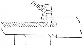
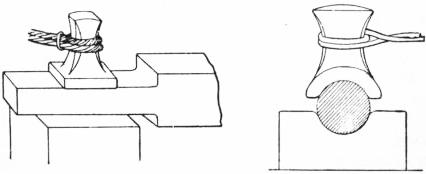
Fullering denotes the preliminary roughing-down of the material between tools having convex edges; swaging, the completion or finishing process between swages, or dies of definite shape, nearly hemispherical in form. When a bar has to be reduced Fullering and swaging. from larger to smaller dimensions, it is laid upon a fuller or round-faced stake, set in the anvil, or, in some cases, on a flat face (fig. 1), and blows are dealt upon that portion of the face which lies exactly opposite with a fullering tool A, grasped by a rather loosely-fitting handle and struck on its head by a sledge. The position of the piece of work is quickly changed at brief intervals in order to bring successive portions under the action of the swages until the reduction is completed; the upper face, and if a bottom fuller is used the under face also, is thus left corrugated slightly. These corrugations are then removed either by a flatter, if the surfaces are plane (fig. 2), or by hollow swages, if the cross section is circular (fig. 3). Spring swages (fig. 4) are frequently used instead of separate “top and bottom tools.” Frequently swaging is practised at once, without the preliminary detail of fullering. It is adopted when the amount of reduction is slight, and also when a steam hammer or other type of power hammer is available. This process of drawing down or fullering is, when practicable, adopted in preference to either upsetting or welding, because it is open to no objection, and involves no risk of damage to the material, while it improves the metal by consolidating its fibres. But its limitations in anvil work lie in the tediousness of the operation, when the part to be reduced is very much less in diameter, and very much longer, than the original piece of bar. Then there are other alternatives.
 |
|
| Fig. 2. | Fig. 3. |
 |
| Fig. 4. |
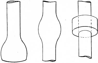
If a long bar is required to have an enlargement at any portion of its length, not very much larger in diameter than the bar, nor of great length, upsetting is the method adopted. The part to be enlarged is heated, the parts adjacent remaining Upsetting. cold, and an end is hammered, or else lifted and dropped heavily on the anvil or on an iron plate, with the result that the heated portion becomes both shortened and enlarged (figs. 5 and 6). This process is only suitable for relatively short lengths, and has the disadvantage that the fibres of wrought iron are liable to open, and so cause weakening of the upset portion. But steel, which has no direction of fibre, can be upset without injury; this method is therefore commonly adopted in steel work, in power presses to an equal extent with drawing down. The alternative to upsetting is generally to weld a larger to a smaller bar or section, or to encircle the bar with a ring and weld the two (fig. 7), and then to impart any shape desired to the ring in swages.
Bending is effected either by the hammer or by the simple exercise of leverage, the heated bar being pulled round a fulcrum. It is always, when practicable, preferable to cutting out a curved or angular shape with a hot sett or to welding. The continuity of Bending. the fibre in iron is preserved by bending, and the risk of an imperfect weld is avoided. Hence it is a simple and safe process which is constantly being performed at the anvil. An objection to sharp bends, or those having a small radius, is that the fibres become extended on the outer radius, the cross section being at the same time reduced below that of the bar itself. This is met by imparting a preliminary amount of upsetting to the part to be bent, sufficient to counteract the amount of reduction due to extension of the fibres. A familiar example is seen in the corners of dip cranks.
 |
||
| Fig. 5. | Fig. 6. | Fig. 7. |
The property possessed by pieces of iron or steel of uniting autogeneously while in a condition of semi-fusion is very valuable. When portions which differ greatly in dimensions have to be united, welding is the only method practicable at the Welding. anvil. It is also generally the best to adopt when union has to be made between pieces at right angles, or when a piece on which much work has to be done is required at the end of a long plain bar, as in the tension rods of cranes and other structures with eyes. The art of welding depends chiefly on having perfectly clean joint faces, free from scale, so that metal can unite to metal; union would be prevented by the presence of oxide or of dirt. Also it is essential to have a temperature sufficiently high, yet not such as to overheat the metal. A dazzling white, at which small particles of metal begin to drop off, is suitable for iron, but steel must not be made so hot. A very few hammer blows suffice to effect the actual union; if the joint be faulty, no amount of subsequent hammering will weld it. The forms of weld-joints include the scarf (figs. 8 and 9), the butt (fig. 10), the V (fig. 11) and the glut, one form of which is shown in fig. 12; the illustrations are of bars prepared for welding. These forms give the smith a suitable choice for different conditions. A convexity is imparted to the joint faces in order to favour the expulsion of slag and dirt during the closing of the joint; these undesirable matters become entangled between concave faces. The ends are upset or enlarged in order to leave enough metal to be dressed down flush, by swaging or by flattering. The proportional lengths of the joint faces shown are those which conform to good practice. The fluxes used for welding are numerous. Sand alone is generally dusted on wrought iron, but steel requires borax applied on the joint while in the fire, and also dusted on the joint at the anvil and on the face of the latter itself. Electric welding is largely taking the place of the hand process, but machines are required to maintain the parts in contact during the passage of the current. Butt joints are employed, and a large quantity of power is absorbed, but the output is immensely greater than that of hand-made welds.
 |
|
| Fig. 8. | Fig. 9. |
 |
|
| Fig. 10. | Fig. 11. |
 |
| Fig. 12. |
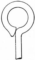
When holes are not very large they are formed by punching, but large holes are preferably produced by bending a rod round and welding it, so forming an eye (fig. 13). Small holes are often punched simply as a preliminary stage in the Punching. formation of a larger hole by a process of drifting. A piece of work to be punched is supported either on the anvil or on a ring of metal termed a bolster, laid on the anvil, through which the burr, when severed, falls. But in making small holes through a thick mass, no burr is produced, the metal yielding sideways and forming an enlargement or boss. Examples occur in the wrought iron stanchions that carry light hand railing. In such cases the hole has to be punched from each face, meeting in the centre. Punching under power hammers is done similarly, but occupies less time.
The cutting-off or severance of material is done either on hot or cold metal. In the first case the chisels used, “hot setts,” have Cutting-off. keener cutting angles than those employed for the second, termed “cold setts.” One sett is held in a hole in the anvil face, the “anvil chisel,” the other is handled and struck with a sledge.
 |
| Fig. 13. |
The difference between iron and steel at the forge is that iron possesses a very marked fibre whereas steel does not. Many forgings therefore must be made differently according as they are in iron or in steel. In the first the fibre must never be allowed to run transversely to the axis of greatest tensile or bending stress, but must be in line therewith. For this reason many forgings, of which a common eye or loop (fig. 13) is a typical example, that would be stamped from a solid piece if made in steel, must be bent round from bar and welded if in wrought iron. Further, welding which is practically uniformly trustworthy in wrought iron, is distrusted in steel. The difference is due to the very fibrous character of iron, the welding of which gives much less anxiety to the smith than that of steel. Welds in iron are frequently made without any flux, those in steel never. Though mention has only been made of iron and steel, other alloys are forged, as those of aluminium, delta metal, &c. But the essential operations are alike, the differences being in temperature at which the forging is done and nature of the fluxes used for welding. For hardening and tempering, an important section of smith’s work, see Annealing.
Die Forging.—The smith operating by hand uses the above methods only. There is, however, a large and increasing volume of forgings produced in other ways, and comprehended under the general terms, “die forging” or “drop forging.”
Little proof is needed to show that the various operations done at the anvil might be performed in a more expeditious way by the aid of power-operated appliances; for the elementary processes of reducing, and enlarging, bending, punching, &c., are extremely simple, and the most elaborate forged work involves only a repetition of these. The fact that the material used is entirely plastic when raised to a white heat is most favourable to the method of forging in matrices or dies. A white hot mass of metal can be placed in a matrix, and stamped into shape in a few blows under a hammer with as much ease as a medal can be stamped in steel dies under a coining press. But much detail is involved in the translation of the principle into practice. The parallel between coining dies and forging dies does not go far. The blank for the coin is prepared to such exact dimensions that no surplus material is left over by the striking of the coin, which is struck while cold. But the blank used in die forging is generally a shapeless piece, taken without any preliminary preparation, a mere lump, a piece of bar or rod, which may be square or round irrespective of whether the ultimate forging is to be square, or round, or flat or a combination of forms. At the verge of the welding heat to which it is raised, and under the intensity of the impact of hammer blows rained rapidly on the upper die, the metal yields like lead, and flows and fills the dies.
Herein lies a difference between striking a coin and moulding a forging. A large amount of metal is squeezed out beyond the concavity of the forging dies, and this would, if allowed to flow over between the joints, prevent the dies from being closed on the forging. There are two methods adopted for removing this “fin,” or “flash” as it is termed, one being that of suppression, applicable to circular work, the other that of stripping, applied to almost all other cases.
 |
| Fig. 14. |
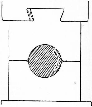
The suppression of fin means that the circular bar is rotated in the dies (fig. 14) through a small arc, alternating between every few blows, with the result that the fin is obliterated immediately when formed, this being done at the same time that reduction of section is being effected over a portion or the whole of the bar.
Stripping means that when a considerable amount of fin has been formed, it is removed by laying the forging on a die pierced right through with an opening of the same shape and area as the forging, and then dealing the forging a blow with the hammer. The forging is thus knocked through the die, leaving the severed or stripped fin behind. The forging is then returned to the dies and again treated, and the stripping may be repeated twice, or even oftener, before the forging can be completed.
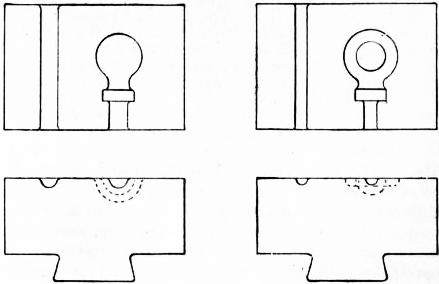
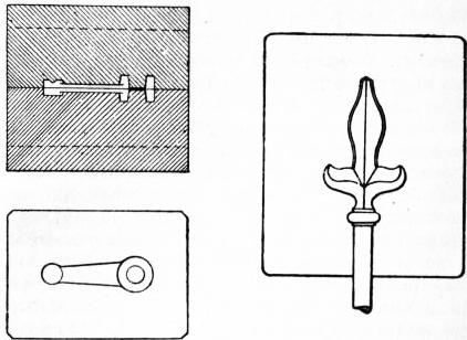
Figs. 15 and 16 illustrate the bottom dies of a set for forging in a particular form of eye, the top dies being of exactly the same shape. The first operation takes place in fig. 15, in which a bar of metal is reduced to a globular and cylindrical form, being constantly rotated meanwhile. The shank portion is then drawn down in the parallel recess to the left. The shape of the eye is completed in fig. 16, and the shank in the recess to the left of that. Fig. 17 shows how a lever is stamped between top and bottom dies. The hole in the larger boss is formed by punching, the punches nearly meeting in the centre, and the centre for the hole to be drilled subsequently in the smaller boss is located by a conical projection in the top die.
 |
|
| Fig. 15. | Fig. 16. |
It is evident that the methods of die forging, though only explained here in barest outline, constitute a principle of extensive application.
An intricate or ornamental forging, which might occupy a smith a quarter of a day in making at the anvil, can often be produced in dies within five minutes (fig. 18). On the other hand, there is the cost of the preparation of the dies, which is often heavy, so that the question of method is resolved into the relative one of the cost of dies, distributed over the number of identical forgings required. From this point of view it is clear that given say a thousand forgings, ordered all alike, the cost of even expensive dies distributed over the whole becomes only an infinitesimal amount per forging.
 |
|
| Fig. 17. | Fig. 18. |
There is, further, the very important fact that forgings which are produced in dies are uniform and generally of more exact dimensions than anvil-made articles. This is seen to be an advantage when forgings have to be turned or otherwise tooled in the engineer’s machine shop, since it lessens the amount of work required there. Besides, for many purposes such forgings do not require tooling at all, or only superficial grinding, while anvil-made ones would, in consequence of their slight inaccuracies.
 |
| Fig. 19. |
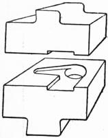
Yet again, die forging is a very elastic system, and herein lies much of its value. Though it reaches its highest development when thousands of similar pieces are wanted, it is also adaptable to a hundred, or even to a dozen, similar forgings. In such cases economy is secured by using dies of a very cheap character; or, by employing such dies as supplementary to anvil work for effecting neat finish to more precise dimensions than can be ensured at the anvil. In the first case use is made of dies of cast iron moulded from patterns (fig. 19) instead of having their matrices laboriously cut in steel with drills, chisels and milling tools. In the second, preliminary drawing down is done under the steam hammer, and bending and welding at the anvil, or under the steam hammer, until the forgings are brought approximately to their final shape and dimensions. Then they are reheated and inserted in the dies, when a few blows under the steam or drop hammer suffice to impart a neat and accurate finish.
The limitations of die forging are chiefly those due to large dimensions. The system is most successful for the smallest forgings and dies which can be handled by one man without the assistance of cranes; and massive forgings are not required in such large numbers as are those of small dimensions. But there are many large articles manufactured which do not strictly come under the term forgings, in which the aid of dies actuated by powerful hydraulic presses is utilized. These include work that is bent, drawn and shaped from steel plate, of which the fittings of railway wagons constitute by far the largest proportion. The dies used for some of these are massive, and a single squeeze from the ram of the hydraulic press employed bends the steel plate between the dies to shape at once. Fairly massive forgings are also produced in these presses.
Die forging in its highest developments invades the craft of the skilled smith. In shops where it is adopted entirely, the only craftsmen required are the few who have general charge of the shops. The men who attend to the machines are not smiths, but unskilled helpers.


